Tag Archives: pcb assembly services

Selective Soldering for PCB Assembly

A selective soldering approach offers PCB connectors the perfect instrument to overcome a few of the challenges. Selective soldering is a robotic device that pushes hot solder from a tank via a nozzle to cover the conduits running from the ground of a circuitry

What is Selective Soldering?

Selective soldering is indeed the method of soldering components selectively onto electronic components and formed modules, damaged in conventional printed circuit board assembly or through-holes technology mounting procedures by heat from the heat exchanger or wavelength soldering. This normally involves an SMT refill operation; selectively soldered components are generally surrounded by elements that have already been supplied in a soldering process and must be accurate enough to prevent damage to them.

Benefits over wave soldering such as no solder pallets are needed:

Wave Soldering is the routine method used for soldering pieces on circuitry for many years. Although originally developed for boards having completely thru-hole parts, some SMT bits will also be soldered.

For TH components to be mounted on circuit boards while PCB manufacturing, selective wave soldering pallets are employed. The pallets are built of an isolated epoxy composites substance. Wave Solder Pallets simplify the production process considerably, removing the need for heavy human work and manual work.

Some situations do not allow wave soldering, and manual soldering is not successful. The only alternative left is to employ the selective solder technique in these circumstances. A few of these requirements include:

  • The high elevation of the component:

The solder wavelength has constraints, and certain components are large enough to obstruct the soldering of the wave.

  • Unanimous heating:

Thick boards, particularly boards with extensive copper layers, might issue manual soldering for power and neutral aircraft. It’s hard to get one molten metal in the board to heat all the electrically coupled metal enough because the solder flows via the holes to make an excellent solder bond.

  • The high-density accumulation of thru-hole connectors:

When big connections with tens of pins are utilized, a soldering iron may hardly be solder efficiently through each pin.

  • Tight spacing of the component:

When thru-holes are too near to SMT components, there may be insufficient space to install a safety fixture around SMT modules to provide efficient wave soldering during smt assembly.

Soldering technology is becoming increasingly 3D, with connections to multiple levels. The maximum temperature is restricted for wave soldering through pallets, and the slurry reflow pin is just a 2D solution with space limits.

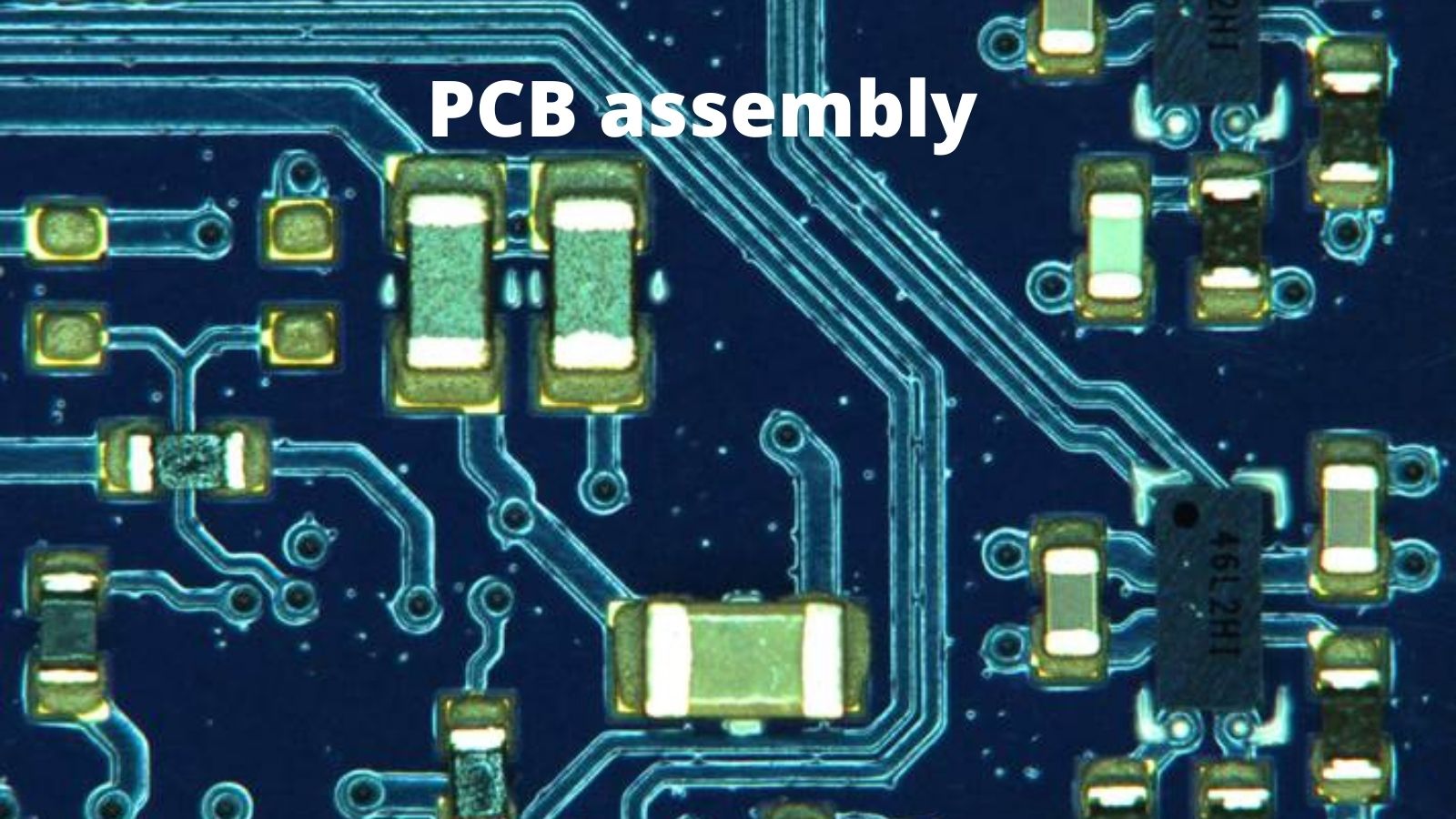
PCB Assembly
PCB Assembly

Selective soldering unit with Nitrogen assisted for clean, shiny solder joint:

Introduction

In these technologies, the major objective of using nitrogen is to avoid creating additional oxide on the solder interfaces of the SelectWave and the MultiWave. Furthermore, nitrogen inhibits the creation of extra dross while cleaning the MultiWave nozzles.

The nitrogen supply surrounding the soldering bottle avoids oxide layer development on the wave exterior and supports the flux action during the soldering operation. The cleaning of the nitrogen must rely on the support needed for the procedure.

Naturally, nitrogen with the greatest purity provides the finest support for the lowest use. But on the other side, less pure nitrogen may also complete the task with greater nitrogen utilization and mass flow. Everything relies on the commodity and the flows utilized.

At PNC, our pcb assembly services will include selective soldering as we have an in-house unit that is nitrogen-assisted for clean, shiny solder joints.

Faster than manual human soldering:

The positioning and soldering of electrical equipment onto circuit boards are also largely dependent on robotics in modern circuit board manufacturing factories. Does it suggest they have passed on to qualified manual assembly engineers? Not really.

As with other production processes, selective soldering is the ideal way for reducing costs and speed. Manual installation needs much-experienced personnel to perform what an electronic soldering line can accomplish more quickly.

Large, dense electronics beneath their pins, including Ball Grid Arrays (BGAs), need automatic solder reflow because of the difficulties of soldering the pins beneath them manually.

  • Large quad flat packs featuring fine-width pins are planarity-sensitive when not all wires are on the surface exposed. This makes it hard to manually solder and prefers automated soldering devices.
  • On the opposite end of the size range, tiny chip equipment, such as resistors and condensers, are too hard for hand positioning and soldering in 0201 containers (or smaller).

ERSA Eco Select 2:

ERSA adds a small ECO SELECT 2 to the renowned VERSAFLOW range as a global expert in selective soldering systems.

This system is particularly suited for modular manufacturing lines and is the perfect answer for small and medium enterprises production when flexibility is vital.

The ECO SELECT 2 is fitted with a programmed elevated flux for specific lines or row flux application, as are other ERSA selective soldering solutions. An incorporated spray sensor monitors the location of the flux stream.

Quick-wave IR emitters on the bottom side enable short preheating procedures. The segments of the heating cassette may be triggered depending on the product. The optional top-sided convection preheater allows even complicated components to be homogeneously warmed up.

The soldering process is indeed the backbone of the ECO SELECT 2. ERSA’s ‘pel off’ effect enables 0° soldering without span development and ensures the minimum DPM rates.

At PNC, we have this facility available and you can even get it at very economical rates.

Features autoload and unload:

At PNC, the process work using the Autoload and discharge system quicker. Our automated smt assembly load/unload decreases the human operation of the worksheet by 80% to enable punching processes more efficiently. The material loads & unloads from the same side of the device to save space. Higher manufacturing stability makes production unattended. There are certain important characteristics;

  • Reduce handling periods by more than 80%
  • Full brush board setup
  • Grips of sensitive part nests.
  • Includes the interaction autoload.

The capability of using leaded solder and lead-free (Unit has two different solder pots):

Lead-free solder has a detrimental effect on connection reliability. In terms of mechanical effect, plumbing solder is tougher than plumbing solder. In addition, plumbing-free soil generates surface compounds, flux impurities, and deposits of alloys that may produce poor surface energy. For these reasons, the change from leading to plumbing-free electronic manufacturing is not a comprehensive substitution of electric and hydraulic features:

  • The lead is rather soft. You will discover that solder junctions without lead are tougher than solder junctions produced by lead. This increases the intensity and tiny changes, resulting in excellent dependability.
  • Free lead soldering creates poor weathering, causing other difficulties, such as vacuum and burial.

Leaded solder offers many advantages for electronic production, but the tides of revolution are furious. All sectors using solder in considerable numbers will probably change to plumbing free shortly if they’ve not yet done so.

Engineers at PNC are experts in designing, pcb assembly, and fabricating customized PCB designs with efficient soldering techniques which are pocket-friendly at the same time.

Contact us at sales@pnconline.com to get the customized quote on your requirements.

Importance of Good ESD Practices in SMT Assembly

The management of electrostatic discharge is a crucial feature in the production, assembly, and maintenance of electronic equipment. If electrostatic discharges are not managed, they may destroy an electrical device at any step of its manufacture or use. Grounding any wires that come into touch with or are close to the electrical equipment is the main way of control. Humans, tools, ESD mats, various electronic equipment, boards, connections, packing, and other conductors are among them. Removal of extra insulators, shielding, ionization, pollution regulations, training, awareness, and highest level compliance are all part of a successful ESD management program.

What exactly is ESD?

The quick current flow between two oppositely charged objects generated by the response to an electric short or insulator breakdown is known as electrostatic discharge (ESD). Tribocharging via electrostatic induction may generate a build-up of high voltage. When different-charged items are placed near together, or the dielectric among them disintegrates, ESD develops, which typically results in a vivid spark. This could result in major part damage during the printed circuit board assembly process.

ESD may generate tremendous electric sparks and less dramatic forms, not seen or heard but strong enough for sensitive electrical equipment to be harmed. Electric sparks need a field strength in the air of more than 40 kV/cm, as seen in lightning strikes. Energy transfer from acute electrodes and brush discharge from flat electrodes are two further types of ESD.

Smt assembly
Smt assembly

What is the importance of ESD?

Exposure to ESD, or the abrupt passage of electricity over two electrically charged items, may cause any electronic device or part to deteriorate. When two differentially charged items brush against one other, an apparent spark is typically produced. Even easy movement on a workstation may cause ESD, which may harm a device’s sensitive electrical components. It may also have an impact on the functioning and quality of electrical devices and components. As a result, ESD protection solutions are critical for preventing the accumulation of electrostatic force in electronic devices. Their primary purpose is to limit the possibility of ESD-sensitive equipment being damaged. These protective solutions are particularly successful in preventing system failure and extending the life of fragile electrical devices.

A pro-EPA (ESD protected area) should be established for the safety of production facilities or pcb assembly workstations. EPA may be enhanced using ESD-resistant goods, including workbenches, commercial furnishings, trolleys, warehouses, etc. Wristbands, conductive straps, and other devices may be worn by persons working in the vicinity to safely disperse ESD. These items are wired to the ground, where an electrostatic charge is dissipated via earthing points and connections. This allows ESD to be dissipated more safely.

ESD Protection Zones in the Facility:

Electrostatic Discharge Shielded Locations (EPAs) prevent ESD-sensitive devices from typical electrostatic discharge sources by grounding conductive objects and personnel in ESD-prone production areas such as:

Pro mats, for example, are conductive surface materials.

  • Staff uniforms and clothing with conductive filaments
  • Optimal humidity levels

Circuits with built-in ESD protection:

When assemblies are most susceptible like during electronic assembly, built-in ESD protection decreases the danger of complete circuit breakdown or latent damage. The following are some of the best practices for ESD protection built-in:

  • Choosing the right short backflow prevention device for your Printed Circuit Board
  • Installing the isolator at the ESD contact site

What is ESD (Electronic Stability Device) Training?

Controlling electrostatic discharge requires ESD training. You recognize the significance of avoiding electrostatic discharge. You already know that in electronics assembly, an ESD control program is critical for quality and yield. Any successful ESD control program and vital to successful electronic manufacturing require an effective, systematic, and long-term ESD training, certification, and re-certification system.

What is ESD 20.20 Training?

Electro Static Discharge (ESD) is a typical phenomenon in which a person or almost any ‘charged’ item emits a brief electrical shock.

The multi-industry guideline for developing ESD management programs that safeguard today’s highly sophisticated electrical parts, assemblies, and machinery from expensive ESD damage and decrease downtime is ANSI/ESD S20.20. An organization may design an ESD control program that protects equipment down to 100 volts or fewer using the format’s control techniques and advice.

The S20.20 standard, which several multinational OEMs use and serve as a successor for MIL-STD 1686, has swiftly gained traction in the electronic, telecommunications, aircraft, automotive, and devices sectors. In reality, the S20.20 standard is included in the telecom industry reference TL 9000 as a recommended practice for addressing ESD control requirements.

A good ESD management program within a printed circuit board assembly facility may help you avoid expensive system failures while also improving customer service. Organizations may use NQA’s ESDA-accredited Site Certification program to guarantee that their programs satisfy the standards and give documentation of conformance for customer marketing reasons.

When it comes to ESD training, there’s a statement that goes something like this:

“Managing an ESD program is an important aspect of a full quality program in the modern electronics sector. Any electronics company that does not have an active ESD program is putting itself or its customers in danger.”

At PNC, all the employees receive annual ESD training based on ESD 20.20.

What Are the Advantages of ESD Training?

Improper handling of today’s electrical components may quickly harm or make them faulty. Furthermore, rejecting or fixing items affected by electrostatic discharge (ESD) may waste time and money for companies that handle electronic components.

  1. Raises ESD awareness in the workplace
  2. Enhances overall performance levels and product control
  3. Lowers the failure rate, lowers rework, and saves money.
  4. Aligns with peers in the electronics industry
  5. Provides consumers with clear evidence during site visits
  6. Controls for ESD (proper clothing, grounded tables, signage, etc.)
  7. Increases marketability and gives you a competitive edge.

What is ESD Audit?

A solid ESD control program should include an ESD audit. It audits all ESD-control processes and products, reminds employees of their obligations regularly, and provides management with the information needed to take remedial action.

An audit is conducted using an ESD control program that has been designed, authorized by management, and applied at all levels of the smt assembly area. In most cases, such software is based on industry-developed standards. ANSI/ESD S20.20-1999, produced and regulated by the ESD Association, is the cost of setting up a document for many programs and is a good option for a guiding standard.

ESD Audit Work Area:

The audit must ensure that the border between ESD-protected and non-ESD-protected locations is properly marked, e.g. signs, directional arrows, and floor markings. This reminds both employers and employees that they enter a critical control environment or leave it.

Supply carts to store or carry ESD-sensitive items should have electrically linked uprights and shelves mounted by a trailing chain to avoid tribo-loading. A floor snap is strongly suggested for strong grounding of the cart when fixed in an ESD safe location.

ESD Practices at PNC Online                           

During an audit at PNC, it was noted that all the employees themselves tested multiple times a day. The company follows all standard patterns for complete ESD audits on an annual basis. PNC employees wear ESD Smocks, wrist straps, foot Straps, and ESD shoes.

3D Automatic Optical Inspection (AOI) for PCB Assembly Introduction

The highest demand used in quality management of electronic printed circuit boards (PCBs) and PCB assembly is automatic optical inspections and automated optical inspections (in short, AOI) (PCBA). AOI inspects the electronic assemblies such as PCBs mechanical visual inspection to ensure that the components of PCBs are in the right place and the contacts are correct.

Automated optical inspection (AOI) is an intelligent visual inspection of the production of the printed circuit board, where all catastrophic failures (such as broken components) and quality faults can be scanned automatically by a sensor.

It is widely used in the production phase because it is a way of testing without touch. It ensures the multi-layer circuit boards provide a high degree of durability.

For the following various applications, it is essential:

  • Infringements of line spacing
  • Violation of spacing
  • Copper excess
  • The shortage of pad
  • Short circuits
  • high frequency
PC board
PC board

What does AOI inspect?

AOI is a primary method used to build and test electronic printed circuit boards and PCBs for automatic or automatic optical inspection. Automated optical inspection, AOI allows quick and precise assessment of electronic assemblies and, especially, pcb assembly to ensure that the standard of goods is good and that the object is appropriately and without processing defects.

What is the need for AOI inspection?

Current circuits are much more complex than boards were a few years back, notwithstanding the significant changes that have been developed. With the advent of surface mounting technologies and more size decreases, boards are exceptionally lightweight. Even comparatively ordinary panels have millions of fused joints, and most issues are observed.

This growth in board difficulty also implies that manual examination is currently not a feasible choice. Even if the solution was approved, the inspectors quickly fatigued it, and poor and wrong design was easily overlooked. With great demand, high-quality goods on the market now require very simple, very stable, and fast.

To ensure that the product quality continues to be good, methods are required. AOI is an indispensable instrument within the context of an advanced electronic test plan, ensuring that the expense is held to the lowest possible levels by identifying faults at an early stage of manufacturing.

Benefits over manual visual inspection

PCB devices switch to ultra-thin, lightweight, higher densities, and exemplary size components. The part assembly width of the circuit board has increased, the width and distance of the Printed Circuit Board -line and the pad are decreasing and reaching the micro-level. The manual process of visual examination cannot be achieved. Furthermore, people seem to be tired and emotionally affected, according to the textbook. Inspection equipment is more stable, repeatable, and precise when it comes to machine vision.

Manual visual examination is a vital part of our BES operation. All new boards, either we order from a new supplier or a well-experienced BES company, are visually inspected by us. From solder masks to solder joints, we test all on the floor. Shipping packaging is also evaluated. When we develop our projects, manual visual testing is also helpful throughout the development, from designing to large-scale production. It was the first phase in our identification and repetition of design or manufacturing problems.

  • The usual general information SMT operator will fit well for quick and easy manual visual inspection.
  • Manual visual inspection with high flexibility;
  • The original costs are minimal, and only the initial Labour costs are spent, and high expenses are not available;
  • Preparation is fast.

How can time save done from the visual inspection process?

Visual inspection proves to be a game-changer, with many apps in almost every domain. The company is now moving into manufacturing and production, enabling them to use the power of profound learning and thus have quicker, safer, and superior automation.

  • More quickly

CPU speeds, as calculated in FLOPs and even accurate measurements, result in observations and conclusions, which are done incredibly quickly.

  •  Accurate

An automated machine can standardize the measurement of absolute measurements.

  • Trustworthy

The machine is impartial and programmable as required and without doubt following instructions. It is undoubtedly a result of this technological transition that is moving global producers into different production and productivity levels.

Final Thoughts

AOI is a vital factor in ensuring the accuracy of your completed electronics items is defective and accurate. It gives a shorter timeframe, more efficiencies, and lower prices, which would have increased if reworking was required.

The AOI process provides reliable monitoring and resulting information which enables improved quality control procedures management and the correction of potential issues. The algorithms will monitor the successful and defective PC Board components and record them. Efficiency is also improved from the point of view of process control, organizational integrity, and reporting.

The controls provide search, identification, and measurements or diagnosis for the outgoing product condition. Inspection is an operation. Tasks of supervision have typically been assigned to people. Efforts to simplify industrial inspections to eliminate mistakes and reduce monotony have encountered technical constraints and cost factors of deployment. A prototyping model is an occasional compromise. Reviews have released new study status on manual, hybrid, and automatic inspection.

Perhaps the most critical inspection process is the visual inspection of the parts made. Draw the section and equate the area with the painting visually. For units with several functions, this is particularly relevant. Anything may go wrong, and one of the several production cycles.

During AOI, optical inspection algorithms usually use visual techniques to ensure defects on written platforms. They can identify a range of material removals, such as nodules, scratches, and marks, as well as known dimension faults, such as open circuits, shorts, and solder integrity. They will also spot faulty components, missing components, and parts that have been misplaced. All system is designed to monitor tests conducted by manual operators can be carried out much quicker and more reliably.

How can We (PNC ONLINE) help you in 3D Automatic Optical Inspection?

At PNC, you will get your design checked from two (2) Mirtec MV-6 OMNI machines which itself is high-speed/high-performance 3D AOI MACHINE FIFTEEN MEGAPIXEL CoaXPress Camera Technology. It has an advanced eight-phase Color Lighting System Ten Micron / Pixel Precision Telecentric Compound Lens. It is designed with an Integrated Ten Mega Pixel SIDE-VIEWER® Camera System Precision Closed Loop AC Servo Drive Motor System which is extremely simple to program and operate. It also has 3D Co-Planarity Inspection – Gull Wing Device with an example as shown below:

PCB Assembly
PCB Assembly

We follow all the system parameters and are set up to meet IPC inspection requirements. Get your Automatic Optical Inspection done for your 3D design at PNC. Contact us at sales@pnconline.com


Work with PNC to Reduce PC Board Costs

When it comes to reducing the manufacturing cost of a PCB, it is important to remember that a significant part of the cost of a PCB assembly is already baked in at the design concept stage.  The product concept defines the PCB size and shape, while the performance of the system dictates the microprocessor, memory and other functional elements of the circuit.

However, some of the assembly cost can still be affected by design choices made by the PCB designer.  A PCB that is designed for manufacturing (DFM) can reduce both the fabrication cost of the PCB and the costs of component assembly and soldering. A DFM approach to design can also reduce the likelihood of the hidden costs of poor yield in production.

The best way to achieve the lowest cost, most manufacturable design is to work closely with the prospective  manufacturer, since the way to maximize DFM cost savings is to design for a manufacturer’s specific equipment and technology, rather than to rely on general rules.

Reducing PCB Fabrication Costs

The first step to reducing costs in PCB fabrication to reduce the number of operations performed by the manufacturer.  The second step is to optimize the PCB design to leverage a manufacturer’s particular fabrication technology.

One way to reduce costs is to eliminate or minimize the amount of machining required around the board edge or within the PCB itself.  Rectilinear PCB outlines without internal slots will minimize machining, and the rectangular shape allows the PCB to be grouped in larger panels that are separated after assembly.  These large panels streamline assembly by allowing a several PCB to go through component assembly and reflow at the same time, improving throughput. For example, PNC can process a maximum panel size of 18” X 24.” To ensure that the components on the PCB are not damaged during the scoring and separation from the panel, components should be kept 200 mil from the board edge.

Reducing board layers to reduce fabrication costs

The generally accepted rule that reducing the number of PCB layers in a stack-up will reduce cost has become more complicated with the advent of HDI technology.   The reason is that the cost of an additional Printed Circuit Board layer is not linear, so a cost calculation needs to be made for each jump in the number of layers. Is it cheaper to use finer trace widths and buried vias to reduce the layer count from six to four?  Only the manufacturer is going to know.  However, as a board gets past eight layers costs increase non-linearly with each additional layer.  The aspect ratio of the through hole vias begin to become a factor, as well as the sheer number of vias that need to be drilled and plated to connect all those layers.   At an eight layer stack up or above, the additional cost of HDI technology begins to make economic sense if it is used to reduce the number of stack-up layers required.

Respect drill to copper clearance and aspect ratio design rules

Respect the design rules for hole sizes and hole to copper clearance.  If the real estate on the PCB allows it, selecting hole sizes clearances and annular ring sizes larger than the absolute minimum will improve fabrication yield. Here are the through hole design rules for PNC:

Non-Plated Through Hole (NPTH)
● Finished hole size (minimum)= 0.006″
● Edge to edge clearance (from any other surface element) (minimum)= 0.005″
Plated Through Hole (PTH)
● Finished hole size (Minimum) = 0.004″
● Annular ring size (Minimum)= 0.004”
● Edge to edge clearance (from any other surface element) (minimum) = 0.009″

PCB assembly
PCB assembly

Reducing PCB Assembly Costs

To reduce assembly costs the objective is the same as reducing PCB fabrication costs; reduce the number of operations, and optimize the PCB design to leverage a manufacturer’s particular fabrication technology.

One easy way to reduce assembly costs is to stay away from the smallest passive packages.  0603 passives are easier to place than 0402 or the almost invisible 0201.  If possible, chose active parts that have leads rather than ball grids, because they are easier to place, they can be visually inspected instead of x-rayed, and they are easier to rework.

Avoid parts that have to be manually soldered.

Manual operations are always expensive, and the designer should do everything they can to avoid the need for them.

Component manufacturers have recognized this and now offer through-hole components (typically connectors) that can be reflow soldered.  This technology called “Through-Hole Reflow” allows through-hole components to be soldered in the same reflow process as the SMD components, eliminating a pass through the wave soldering machine or manual soldering.

Finally, if possible, avoid putting components on both sides of the board.  The cost of a higher density PCB with components on one side may be cheaper than a lower density PCB with components on both sides.

Don’t wait until the PCB design is finished before talking with PNC

The best time to talk with the PC Board design experts at PNC is early in the layout process.  They can tell you when to use HDI to reduce costs and can advise on how to optimize panel size. The experts in the assembly department can also work with you to select components that will reduce assembly costs and increase yield.

Give PNC a call today.

Embedded software development along with PCB Assembly

No company can excel at every aspect of new product development and trying to do everything can dilute an organization’s focus on the tasks that are essential to its success. For example, most companies have long ago outsourced the PCB design and fabrication steps of new product development. This same need to focus on the essential is true of software development too. It is difficult for a software company to excel at every type of software development because of the ever expanding universe of software languages, operating systems, and architectures.  A cloud based SAAS or PC based application is very different from embedded software running C on a 16-bit processor, and it takes very different software development skills to develop that kind of embedded application.

Unlike cloud based or PC based applications, embedded software is optimized to run on a specific custom hardware platform with limited processing power and memory.  It often runs on a real time operating system or no operating systems at all, and the interface of an embedded device may consist of only a small display, or just a few buttons and LEDs.

The unique challenges working with embedded systems is why many software companies outsource their embedded software projects to experts like PNC.  Here are three reasons why they do.

The embedded system is not the organization’s primary product line.

Many products on the market require options or accessories that are important to the customer, but not are not similar technically to the primary product. A cable set top box remote is a good example.  Customers expect a cable set-top box to have a remote, but the low power microcontroller embedded in the remote is likely to be completely different from the high power processor and OS driving the set-top box functions.  Similarly, Industrial or commercial equipment may have optional modules to provide additional functionality like a cellular modem.   These optional modules have independent processors and embedded software which is unrelated to the primary product software.

In these cases, software companies will choose to focus their development resources on the primary product, recognizing that it is more cost effective to outsource the software development for the ancillary embedded products to a company that is familiar with embedded microcontrollers and the constraints that come with low power operation. If that company can design the hardware and perform SMT assembly too, it becomes an even better value.

Embedded software development along with PCB Assembly

The software is deeply embedded and invisible to the user

Successful software companies are highly focused on the customer experience with their product. They are constantly refining the look and feel of the industrial design and user interface to make the product more attractive, and easier to use.  But what if the product doesn’t have a user interface?   What if it is a router or a motor controller?  Products like these need a simple interface for initial configuration, but they typically operate in the background, invisible to the customer.  In this case the goal is to optimize for cost and performance rather than user experience.  Deeply embedded applications without a sophisticated customer facing interface  are ideal to outsource to a company like PNC because the product requirements are centered on the embedded functionality – there is no need to maintain the same look and feel as the company’s customer facing products.

The application requires specialized expertise

 Sometimes a software company needs embedded expertise that it just doesn’t have in-house.  For example, they may need a Zigbee or Bluetooth RF stack, or expertise with digital signal processing on low power Digital Signal Processors DSP.  In some challenging embedded applications, a company may need a partner with the expertise to  iterate the design of both the hardware and software simultaneously to arrive at an optimized embedded solution.  In that case you need a full service provider like PNC.

PNC offers the full solution to developing embedded products

When it comes to product development, PNC is not just a PCB manufacturer.  The engineers at PNC can work with you to design and manufacture the product hardware, and then develop the embedded software to run on that hardware.   If you have a challenging embedded software or hardware project, contact PNC today and find out how they can help.