Tag Archives: pc board assembly

Flexible Printed Circuit Board Overview

Introduction

On a slightly less romantic level, it would not be feasible to have such a standard laptop or mobile phone without flexible print circuit technology, which enables components to be linked electrically, in a dynamic, three-dimensional fashion. Flexible circuit technology has a long history that dates back over 100 years. The early patent activity emphasizes the fact that inventions such as Thomas Edison, Frank Sprague, and others in the early twentieth century experimented on ideas for flexible circuit materials and designs that were only used on a commercial basis in recent decades.

Background

Flexible printed circuits (FPCs) are the heart and soul of flexible films and thin layers of conducting traces. These typically represent the flexible circuit laminate base that can be used to connect electronic equipment – such as the LCD screen or a laptop’s keyboard – as a reliable cable replacement, or electronic components can be directly fitted to it through solder or conductive adhesive to form a completed, flexible printed circuit board.
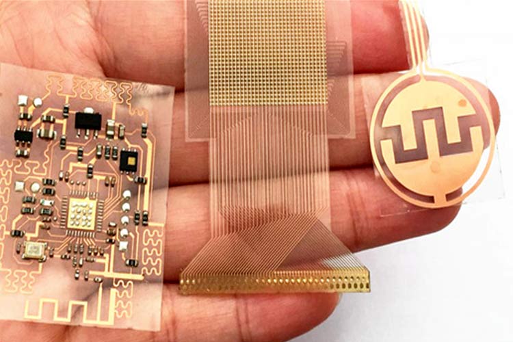
Flexible printed circuits

Flexible PCB advantages

Flexible, FPCs may be bent and curved to provide more flexibility of application design and operation. Flexible circuits may also be adapted to tiny or inappropriately shaped areas, which cannot be supported by conventional rigid circuits. There is another benefit of flexible PC Board is that to reduce the weight of the motherboard of the application, they need less space. The effective utilization of existing areas also helps to improve thermal management and reduce the dissipation of heat.

Flexible PCBs may also be more dependable and longer-lasting compared to stiff PCBs, particularly in situations where constant vibration and mechanical stress are experienced. Based on soldered wires and hand-connected connector models, standard connecting methods are replaced by flexible printed circuits, with exceptional weight and thickness, and with strong mechanical resistance.

Think for example of connecting numerous electronic equipment, such as dashboards, display, and man-machine interfaces, in the automobile industry (rotary controls, buttons, etc.). All these gadgets are exposed to constant mechanical strains and vibrations and need a stable connection in all vehicle operating circumstances. Flexible printed circuits ensure zero reliability, durability, and maintenance in the automobile industry.

Flexible PCBs
Flexible PCBs

Flexible printed circuit boards provide a variety of possible advantages including:

  • Flexible PCBs provide cost-effective benefits that include decreased requirements for materials and packaging, reduced component replacement costs, and assembly mistakes that may lead to repair requirements.
  • These advantages make flex PCBs suitable for a broad variety of sectors, including consumer electronics, transport, medical, communications, military, automotive, industrial applications, and aerospace.

Missing Dielectric Material Callouts

Flexible and stiff flexible circuits are made utilizing a variety of material types to satisfy a broad range of physical and electrical costs and performance criteria. Because of this variation, the designer must give comprehensive information on the dielectric materials to be utilized about the potential problems associated with each choice. It is suggested that designers learn about the cost and performance options available. The Internet is filled with information about flexible circuit materials and how they may be utilized. This issue may also be helped by the PCB manufacturer. The fundamental kinds of flex materials are:

  • Adhesive materials without acrylic binding the copper to dielectric polyimide
  • Adhesive materials with acrylic copper bonding with dielectric polyimide
  • Flammable and non-flammable laminates, covers, and bonding flakes.

Incomplete or Insufficient Rigid-Flex Base Material Type Definition

The selected base material determines the rigid-flex circuit’s performance limitations in-process and field operation in many applications. For most solders devoid of plumage, the highest temperature requirements for soldering may be as high as 260°C, which usually requires the use of polyimide laminates. The choice of material and its electrical characteristics may, however, influence other performance problems.

One important issue is to control the characteristic impedance of the system and guarantee signal integrity with increasingly prevalent designs of higher-frequency circuits (these latter subjects will be given more attention later). The requirements for the temperature range of the stiff laminates used in rigid-flex structures must also be taken into account and handled. The stiff material should be capable of high temperatures. Polyimide laminate is a frequent callout, although epoxy resins are often appropriate for better applications.

Copper Type and Thickness Callout

Whilst many metal foils are available for flexible circuits, copper is the most frequently utilized metal for electronic interconnections. It is extremely conductive, mixable (making it flexible and foldable), reasonably easy to manufacture via graving and placing, and relatively cheap. The copper type most often used for flexible circuits is roll and copper (RA copper) with the greatest characteristics for dynamic flex applications.

The choice of type and thickness for the copper design should correspond to the electrical and mechanical requirements for use. Thicker copper is usually utilized for greater energy and thinner copper for circuits requiring repetitive bending (dynamic flexing). The options of thickness are many, but at present, one ounce (17μm or 0.7mils) and one ounce (35μm or 1 mil) are the most utilized for creating flexible circuit laminates. Additional copper may often be placed on the circuit, and this should also be taken into account in the specification. If the designer is unsure, he should seek the assistance of engineers for advice.
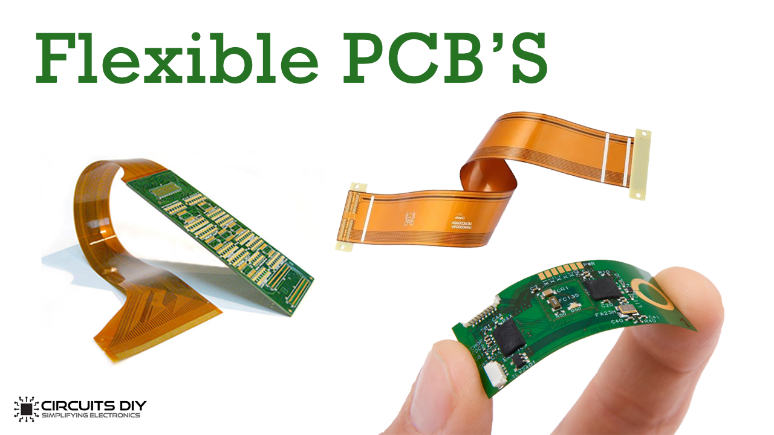
Flex Circuits
Flex Circuits

Cover layer or Solder Mask Over Flex Circuits

Covers are polymer materials used for the covering and protection of the copper traces of the flex circuit product. As is indicated, many solutions for the protection of the circuits are accessible and they meet various design criteria in terms of cost, performance, and flexural durability optimization. It is essential to describe the choice not only of the kind of cover material but also of the thickness required. This may be extremely significant for certain building types, especially when a flex circuit experiences dynamic flexing during usage.

As far as costs are concerned, a flexible solder mask is usually the cheapest. Someone or two-layer flexible circuits, which are not subjected to repeated flex cycles or severe radius curves, may be covered with a solder mask epoxy-based to flex without breaking. However, this is not advised if the design needs severe or dynamic flexing.

The second choice is the laminated cover. These materials are usually identical to the flexible core materials and are best suited for flexible dynamic circuit applications. The cover is a polyimide sheet with one side acrylic adhesive. It is usually pre-machined to open the sheet where the final finish is needed.

The cover sheets are typically coated with specific pads in a laminating machine to ensure that the copper characteristics of the flex layer are conformed. For rigid-flex circuits, the overlayer is usually reduced to not exceed 50 miles in the rigid part. The aim is to ensure that all the plated holes in the stiff-flex are empty of any acrylic adhesive, since they may influence the integrity of the hole wall plating.

Flexible Printed Circuit Board disadvantages

Although there are many significant benefits, the FPC technology also has several inconveniences or downsides. First and foremost, FPCs have significant one-time startup costs compared to conventional rigid PCBs. The initial expenses associated with the circuit and prototype design are greater than for rigid PCBs because flexible systems are developed for highly particular purposes. If the cost is a deciding factor in the choice of the kind of PCB, the use of FPC technology is preferable only for not too low manufacturing quantities.

The difficulty of fixing or changing the PCB when it is rebuilt is another drawback. In this situation, in reality, the protection film that covers the circuit must first be removed, the procedure carried out and protection restored. In order to provide their clients with this kind of product, flexible PCBs are quite a new technology and not all manufacturers are prepared. Moreover, considerable care must be exercised during the assembling stage, because the circuit may be easily destroyed by improper handling or by unauthorized people.

Structure

The historical electric connection methods have been revolutionized, typically for connecting various portions of the same circuit or different electronic devices by introducing flexible PCBs. The flexible PCB-based solution enables significant space, weight, and costs to be reduced compared to an equivalent solution using rigid PCBs due to its flexibility and compactness as well as the high density of electrical connections available. Many kinds of cable systems, frequently manual in multiple applications, have been replaced with flexible printed circuits which reduce overall electrical cable costs by up to 70%.

Interested in getting your Flexible PCB design ready at economical rates in USA? Get it done at PCNONLINE.

Final Thoughts

In the last few years, the FPC business has expanded significantly led by the development of wearable and electromedical devices that are increasingly tiny and light. Flexible PCBs may remove connector and cable requirements in many applications, enhance connection reliability and reduce assembly time, assembly cost, and total device sizes. We can state that flexible PCBs have enabled new in conclusion, fascinating applications to be implemented that are not possible with conventional rigid PCBs.

Flexible printed circuits, from cars, VCRs, camcorders, cell phones, and SLR cameras up to the complex military and aviation systems, are present in all areas. There are numerous high-profile uses of flexible circuits. One example is the employment of flexible-circuit technology in the Sojourner, a robot that explored the Mars surface and collected data in the summer of 1997, in the stiff flexible wire harnesses employed.

Do you have any further questions? Feel free to write us at sales@pnconline.com

Lead Vs lead-free soldering for PCB assembly

What is soldering?

Solder is the name for bonding metals. Soldering is a crucial aspect of the electronics industry, as it is the basic method of connecting electrical equipment to a PC Board. You have to heat the metal at a high temperature and join the parts, and then it will create a perfect electric connection between them when it cools.

soldering
soldering

Differences of leaded and lead-free soldering

Wetting:
Another distinguishing feature is the difference in moisture content. Wetting refers to how well-molten solder paste adheres to the board’s components on the Printed Circuit Board. Solder that has been improperly wetted appears grainy and dull. When using lead-free solder, wetting takes longer and results look dull. Traditional lead solder connections, on the other hand, are usually gleaming and spotless. Inadequate wettability is hazardous to a PCB’s joints. It causes poor joint performance and high circuit board rejects rates.

Changes in melting point:

Lead and lead-free solder perform differently in terms of performance. The melting point difference is the first distinction. Lead-free solder necessitates the use of some of the most extreme iron temperatures. It would be best if you were prepared to wait extended dwell periods due to the high melting points.

Various ranges of temperature:

There is a performance difference between the two due to the differing relevant temperature. High soldering iron temperatures are required for lead-free solder. When it comes to lead solder, however, this is not the case. In comparison to lead solder, lead-free solder requires somewhat higher remelting temperatures.

Raw material:

The raw materials are the essential distinction between lead and lead-free soldering. Flux is used in the creation of both of these items. The addition of lead solder paste is referred to as a lead change. However, when lead-free solder paste is added, it is referred to as lead-free flux.

Uses are different:

The difference in usage is the next distinguishing feature. Lead solder is frequently used in hobbyist projects. These projects are exempt from the RoHS regulations. On the other hand, lead-free soldering is required for major projects that must adhere to RoHS regulations.

Different appearance:

The look of lead-free solder junctions is grey, harsh, and uneven. The majority of leaded solder junctions, on the other hand, are bright and neat. They have a refined and gentler appearance. Lead solder is also somewhat heavier than lead-free solder in terms of density. Lead-based solder weighs 8.5 gm per square meter, while lead-free solder weighs 3.5 gm per square meter.

Advantages of lead-free solder

Due to the dangers of lead, lead-free solder has become common in electronic businesses and manufacturers. In the electronics sector, the Restriction of Hazardous Substances directive (RoHS) went into force, banning lead in consumer devices manufactured in the E.U. Manufacturers in the United States may be eligible for tax breaks if they reduce their usage of lead-based solder. The use of lead-free solder was generally accepted before lead-free solder being common in consumer-produced products. Almost all electronic assemblies were built to survive the usage of lead-free solder and the temperatures needed for manufacture.

Many users were fearful that lead-free solder would not last besides lead-based solder and those goods would fail. Because its characteristics are less well understood, lead-free solder might be not so much attractive for sensitive programs like aerospace and innovations in the field of medicine. We’ll see whether lead-free solder stands the test of time as it becomes increasingly popular and needed.

The decision of lead-free materials for wave soldering or through-hole soldering is based on the final completed PCB assembly unique design specifications and product demands. Even though lead-free soldering requires extreme temperatures, careful board architecture and material selection will be critical to avoid metal decomposing or harm critical electrical parts. This is particularly true throughout reflow when heat waves exist for long periods.

Disadvantages of lead-free soldering

Temperate:
Compared to leaded soldering, it needs low temperature to melt. Lead-free soldering requires high temperature. It needs around about 217°C/422°F temperature to melt. Electrical devices and PCB materials must be able to endure extreme heat.

Hard to handle:
Though lead-free solder operates perfectly there are several instances when lead solder beats lead-free solder. To begin with, lead solder is quite simple to work with. Even if a child ingests or consumes it, the poisonous substance is absorbed by the body.

Surface energy:
The absence of surface energy is perhaps the most significant disadvantage of lead-free solder. External pressures cannot be resisted by lead-free solder. The components may easily fall off if exposed to severe conditions.

Soldering irons with high wattage:
When lead solder is used, there are fewer quality issues with the head Soldering irons with high power are required for lead-free soldering. You may injure your head as a result of this. Again, this may lead to problems with your board’s quality. When you select lead solder, however, this is not the case. You may need to remove the head fast because of the high soldering temperature needed for lead-free soldering. When the use of lead soldering, however, you can prevent such a situation. This is something that many circuit designers are aware of.

Pcb Assembly
Pcb Assembly


Get it done at PNC Inc. Just contact us at sales@pnconline.com

What is a Keyboard PC Board

What is a Keyboard PC Board?

Introduction

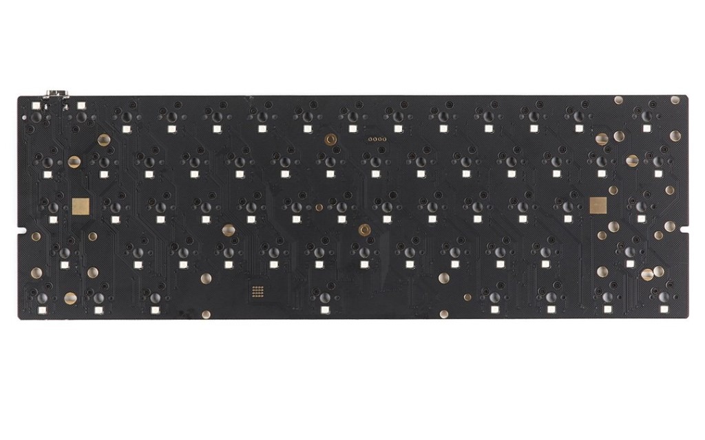
As all other things are the same, a plate-assembled keyboard is more robust than a PCB assembled keyboard and has a stronger feeling. The overall quality of the keyboard and its case play, too, although it differs from a plate of aluminum or steel between the typing of a laminate sheet (PCB). (It’s possible, but very rare, to have a plastic plate on a mechanical keyboard.) In contrast, the PCB-mounted keyboards usually have a bouncer key feel and a more flexible case and creakiness. It is safe to say that plate-mounted keys are generally more high-quality than PCB-mounted keyboards, although not all of them like to feel. Some people like to give extra in PCB-mounted keyboards.

pc board
pc board

Kinds of mounting styles

There are two kinds of mounting styles when purchasing switches for your mechanical keyboard: PCB mounted and plate mounted. It may be difficult to determine the distinctions, so let’s clarify what they imply. PCB-assembled switches have five pins, whereas plate-assembled switches have three pins. By cutting off the extra pins at the bottom of the switch, you may convert the PCB mount switch to fit a plate mount.

What is a PCB-mounted switch?

Since there are a total of 5 components to the bottom of them, PCB-mounted switches are 5-pin. Look closely at the base of the PCB-mounted switches, and you will discover a total of 5-pin switches. The five pins consist of 2 plastic pins on the edges, which provide the switch rigidity, two metal pins, and a “pin” in the middle, which appears more like a circular or big handle. The switches, as illustrated below, may be soldered to the PCB and installed easily.

By using two metal pins on the sides and two plastic pins, the switch operates, thus giving stability, and one center “pin” appears more like a big round button. To assist the Printed Circuit Board in attaching, the switches additionally include guide pins. In this kind of installation, the keys tend to bounce a little more as well as often have a lighter feel. As they are less flexible and need less structure to stay together, the PCB mounting method is utilized with smaller keyboards in general. However, having a plate is quite prevalent in contemporary boards. Besides soldering quality determines the stability of the switches, you may opt to construct a keyboard without a plate.

Pcb mounted switch
Pcb mounted switch

As far as PCB-mounted switches are concerned, there are guide pins that assist install the switch on the PCB. The keys may jump back a little more, and this kind of assembly usually has a lighter atmosphere. This amount is mostly used in a tiny keyboard since it requires less structure and less flexibility. Nevertheless, a plate is very common in the present board. Soldering quality determines the stability of the switch, without a plate you can easily build a keyboard.

Plate-mounted switch

They are called Plate-assembled switches as they need a plate. At the base, it contains just three pins, the two metal pins, and the center circular pin. They do not have stable pins. This is where the plate enters. The plate stabilizes every switch and reduces swaying side-by-side when the key is pushed. It is constructed with a plate since the stabilizing pins are not available.

Plate-mounted switch

Plate-Mounting VS PCB-mounting

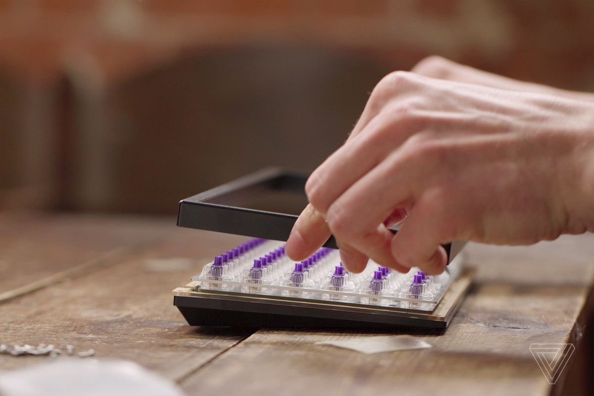
When the key is pressed down (as shown below), after placing the switches on the metal plate, they are soldered to the PCB. The plate enables the keyboard to seem stronger and sturdier with a heavier sensation.

Plate Pcb
Plate Pcb

The switches must be installed on a metal plate that is placed on the PCB with regard to plate installation at the time of PCB Assembly. Following installation in the metal plate, the switches were soldered to the PCB. In order to become stronger and sturdier with a harder feel, the plate enables the keyboard. In order to provide additional support, these are used frequently in a larger keyboard since the keyboard is bigger and more flexible. To preserve things better, the plate also provides more solidity to the keyboard.

A key difference among plate-mounted PCB-type switches is that as they are mounted on the plate instead of the PCB, they do not need additional guiding pins. Just note, when the switches are soldered, the plate will be hard to pull off. You should remove it and solder it back to your PCB. It should be removed. This will probably not be beneficial if you wish to make adjustments and modifications.

While noticing the number of pins on the bottom to examine the major differences between a plate-mounted and PCB-mounted switch. There will be five pins on the PCB-mounted switch, whereas three on the plate-mounted switch.

The plate is typically extremely durable and of higher quality. Since it makes the key more solid and less harsh, some people like the feel of this mounting technique. Due to the additional components and assemblies, this design is typically more costly. There are two mounting styles of mechanical keyboard switches: mounted on a plate and mounted on PCB. The difference may be difficult to sort. Therefore we will explain both changes in this post more fully. The platform-mounted switches have just three pins; the platform-mounted switches have five pins. By removing extra pins on the bottom portion of the switch, you can convert PCB-mounted to fit with plate-mounted switches. In this article, we will show you to suit your board to modify the switches and explain the difference between various kinds of switches. These plates are frequently used to support bigger keyboards because the additional size makes the keyboard more flexible. The plate also provides additional stiffness to the keyboard and helps to secure everything.

3-Pin Vs 5-Pin Switches

Firstly, if you utilize switches without a plate, your switches have less bolster at that point. The keyboard seems shakier and less stable because of the lack of support. You might need to put a plate on your keyboard if you are a heavy-handed keyboard user or want to have a permanent keyboard experience.

In general, the PCB-mounted design needs no additional supporting plate. Thus the building is less expensive and simpler. They mostly carry 3-pin switches on many hot-swappable boards. It may be helpful in such a situation with 3-pin switches. If you produce a bespoke keyboard, it’s carefree because you may choose whatever PCB you are using. You have to put them in a 3-pin PCB; it is not difficult to make them appropriate whatever you buy 5-pin switches.

As we have already established, the main difference between 3 pins and five pins is that of total pins. With either a fingernail cutter, tissue cutter, a nail trimmer, or other normal equipment around the home, you may cut the two plastic pins side by side.
What is the meaning of the Keyboard Plate? The plate is utilized for extra support over the PCB, which makes the keyboard more stable and flexible. This component is usually not held by every keyboard. Thus, whether or not they have this plate, it can be known as the major difference between the two switches mounted.

Preferred Keyboard Choices

The ultimate option with your board is the keycaps. Like the switches, here you have a wide option, and whomever you are going with will ultimately be your taste for how they appear. By saying that, certain basic principles are useful to remember, notably, what type of plastic your keyboards make of and how they are printed (or “legends”).

Preferred Keyboard
Preferred Keyboard

ABS plastic and PBT plastic are your two major choices in terms of materials. PBT keycaps are usually somewhat more durable and will not wear off and shine as quickly. The disadvantage is that they are usually more costly.

Conclusion

In this article, we reviewed all the distinctions between PCB-mounted and plate-mounted switches. Whether they are five pins or three pins, these are primarily differentiated on the bottom of the switch by the number of pins. Since you can easily remove the additional plastic pins, the number of pins does not change too much if your PCB just installs the mounting method of three pins. We have also explained the PCB keyboards in the modern-day that helps in constructing a clavier using a plate vs a PCB mounting method, such as differing feelings, quality, and rigidity.

There are many PCB kinds, all of which provide a distinct typing experience and features that demonstrate how deep this interesting pastime is. A keyboard is connected to a PC. But both kinds of keyboards have their advantages and disadvantages. When you go to your local PC store, consider the differences between mechanical and membrane keyboards carefully.

Should you have any queries, feel free to contact us at sales@pnconline.com
PCB FABRICATION SUBSTRATES

PCB FABRICATION SUBSTRATES

What is PCB substrate?

Every home is required to have a solid foundation. A substrate is also required for every printed circuit board. The actual substance that contains the traces and elements is known as the PCB Fabrication substrate. The first step in creating a high-quality PCB is selecting the correct substrate. Structure and shape are required for a PCB. It also requires a platform or canvas on which to place all of its other components. The PCB’s performance is influenced by the substrate’s properties. A stiff substrate, for example, can improve the PCB’s strength and endurance. More design options are available with a flexible substrate.

The usage of a variety of substrates, ranging from solid fiberglass to flexible polymers, is becoming more common as the PCB industry evolves. Fiberglass has traditionally been the most prevalent type of substrate. It’s a low-cost, high-reliability material that gives the PCB a nice, stable foundation.

pcb board
pcb board

 Material of PCB substrate

It’s only reasonable that the materials you choose have an impact on your product’s performance. It’s the same with printed circuit boards, where selecting the correct PCB substrate materials can have a significant impact on the board’s performance, durability, and other characteristics.

printed circuit board

Types of PCB substrate material

Following are the good material that we need for PCB substrate.

1. Copper foil:

PCB substrate materials are critical in defining the board’s endurance and quality. Manufacturers appear to be attempting to go towards fine lines and high density. You may be familiar with the term HDI PCB. This is the abbreviation of High-Density Interconnect Printed Circuit Board. To be classed in the HDI category ten years ago, a board had to have a line space (S) and line width (L) of less than 0.1mm. Today’s standards differ from one industry to the next. S and L on electronic devices are frequently set as low as 60m, and in advanced applications, they can even go as low as 40m. Once a thin copper foil substrate is applied, S and L can reach as low as 30m during circuit design development. The ideal thickness is between 9 and 12 meters.

The issue is that a thin copper-coated laminate can be costly and prone to flaws. It’s the most plausible explanation for why corporations use 18-meter-thick copper foil. However, if S and L are less than 20m, normal thickness copper foil may not be the best option.

pcborard
pcborard
 2. Dielectric Insulating Coatings:

The ability to build up is a key feature of HDI printed circuit boards. There’s a good probability you’ll be able to construct an appropriate circuit if you utilize resin-coated copper (RCC) or combine copper foil lamination with epoxy glass prepreg cloth. MSPA and SAP techniques have also been implemented by the manufacturers. By using an insulating dielectric film lamination with chemical copper plating, the copper conducting plane was created. The fundamental reason we can make acceptable circuits is because of the thin copper plane.

3. High heat protection and dissolution are required:

Electronic devices tend to generate more heat as the trend toward downsizing and high function continues; hence thermal management of electronic devices is becoming increasingly important. Thermal-conducting PCB research and development is one of the solutions to this problem. The main criteria for a PC Board to operate well in terms of heat resistance and dissipation are the substrate’s heat resistance and dissipation capacity. Improvements in thermal-conducting capabilities of PCBs are now being made through epoxy and filler additions; however this only works in a limited category. The most common way is to use IMS or metal core PCBs as a heating component. This system has several advantages over the typical radiator and fan, including a smaller amount and lower cost.

How to Select Substrate Materials for PCBs

You can choose between three distinct types of PCBs:

• Rigid
• Flexible
• Flex-rigid

The most important goal is to select a board that is ideal for your product. Many people strive for compact size and shape while overlooking performance. Polyimide film is a good choice since it is adaptable and can be used in a variety of applications, including black, white, and transparent. It also ensures a low coefficient of thermal expansion while keeping acceptable heat resistance. The Mylar substrate, on the other hand, is extremely flexible and resistant to external conditions. Furthermore, it is reasonably priced, which is why many consumers consider it. Flexible PCBs must attempt to achieve the same degree of frequency and speed performance as regular PCBs. Flexible boards can be made with advanced polyimide substrates and polytetrafluoroethylene.

Flexible boards are used in a variety of industries, including medicine, smartphones, and gadgets. As a result, the market has been implementing innovations in flexible and ultra-thin multi-layer boards (0.2-0.4mm). You can expect flexible boards to achieve speeds of up to 5Gbps at this time, but you’ll need to choose a substrate material with a low Dk/Df. It’s also a good idea to utilize conductors with a thickness of above 100m, as this will aid with current and power handling.

Best PCB substrate type

A substrate and printed wires are the two main components of a PCB (the copper traces). Substrates that divide the layers are required for multi-layer boards. The substrate works as physical support for the circuit components and printed wires, as well as providing electrical insulation between conductive portions. PCB Substrates are non-conducting materials. They act as a laminated electrical insulator between circuits for this purpose. An electrical insulator is a material that does not conduct electricity because its internal electric charge does not flow freely. As a result, plated through holes are used to connect traces on opposite layers on each layer of circuitry.

A substrate and laminate are commonly used as the foundation or base of a printed circuit board (PCB). The performance of the PCB is determined by the type of laminate and substrate used. As a result, choosing the proper types of PCB material for the job is crucial to getting the greatest results. Any PCB design guide should include such features:

 Working
 Durability
 Cost-effectiveness

The material you choose for your PCB can have an impact on its short- and long-term functionality, along with your contractor’s capacity to build it. You can’t blame the contractor if you buy substandard materials and they fail when your contractor tries to make the board. When maximum performance isn’t a must-have feature for a PCB, lightweight polyester material is typically a fine option. As long as lightweight polyester is utilized in conjunction with printed electronics (PE) technology, there are at least two reasons to choose it in these circumstances. Printed electronics with lightweight polyester have these features:

Cost-effective Lightweight polyester produces less waste, necessitates fewer manufacturing steps, and eliminates the need for desalination and purification.

Adaptability Flexible printed circuits (FPCs) are available, but the level of “bendability” that makes them so appealing is costly to accomplish. PE with lightweight polyester maintains flexibility at a far cheaper cost.

Traditional PCBs, on the other hand, is still the top choice for high-performance applications, and the materials used in their construction should be determined by the type of board required. For example:

 Manage frequencies ranging from 500MHz to 2GHz
 Allow for high power and, as a result, high temperatures
 Be “intense” and complicated
 Manage microwave and above-microwave frequencies

The board’s application decides the substrates and laminates to utilize to a considerable extent. There are five types of substrates, each with its own set of features for specialized purposes.

1. FR-4

Fiberglass substrates are comprised of woven fiberglass that has been impregnated with only a flame-retardant substance. The material is rigid and can be drilled, cut, or machined, although tungsten carbide tools are required due to the abrasive nature of the fiberglass. An FR-4 substrate is more resistant to cracking or breaking than an FR-2 substrate and is typically seen in higher-end devices.

2. RF
Low dielectric polymers are employed in RF substrates, which are used in printed circuit boards for high-power radio frequency applications. Despite its low mechanical qualities, the substrate exhibits remarkable electrical performance.

3. FR-2
This extremely low substrate is comprised of impregnated paper, also known as Phenolic, and is simple to the machine over a fiberglass substrate. Flame Resistant is denoted by the letter “FR.” This substrate is commonly encountered in lower-cost consumer devices.

4. Flex
Flex circuits are those that are meant to be very flexible or slightly flexible. As substrates, thin, flexible polymers are used. Although the manufacturing process is more complicated than utilizing rigid substrates, it provides benefits that rigid substrates cannot, such as reducing space by bending the circuit board to fit a specific place or where repetitive action is essential. A low-thermal resistance substrate is required for power electronics. A ceramic core or metalcore substrate has the essential properties to accommodate larger copper tracks and the high electrical currents that these circuit boards require.

Final Thoughts

Every substrate has its uniqueness and you get to know almost every substrate detail in this write-up. Interested to know more about our facilities at PNC? Contact us at sales@pnconline.com

Smt Assembly Conformal Coating

SMT Assembly Conformal Coating

Definition

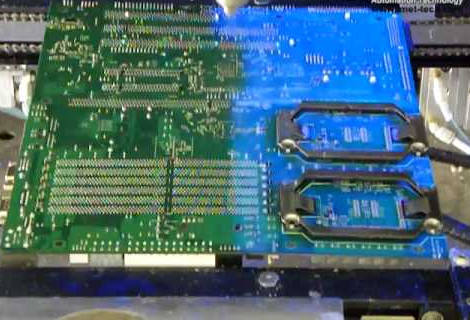
Conformal coating is a thin layer of protected polymeric coating applied to printed circuit boards (PCBs) and electronic components. Its goal is to provide environmental and mechanical protection for the components and circuits, allowing them to last longer and be more reliable. It maintains long-term surface insulation resistance values by being electrically insulating, ensuring the assembly’s operational integrity. It also prevents corrosion by acting as a barrier to airborne pollutants from the operational environment, like salt spray.

Conformal coatings are often applied in the 25-250 micron range. Parylene films, on the other hand, are applied significantly thinner and can be fractions of a micron thick. Conformal coatings are a flexible covering that will secure the printed circuit board assembly from the environment it is in by filtering out air pollutants and ensuring long-term interface resistance value while also allowing any moisture trapped in the circuit board to dissipate.

The notion of conformal electronics coating was first conceived and refined through research decades ago to suit the rigorous requirements of the military. HumiSeal was a pioneer and leader in that early research and the company has remained a pioneer and leader for over 60 years as the technology has spread to a variety of industries, including:

  • Industrial Controls
  • Automobiles like Hybrid and Electric Vehicles
  • Aerospace
  • Telecoms
  • Traditional and renewable energy
  • White thing

 Conformal coating types

While there are many other types of coatings, including a few specialist forms, five primary categories are depending on the chemical makeup of the substances.

  1. Urethane Resin (UR):

Single-part or two-part urethane resins are available. It is chemically resistant as well as humidity resistance. On the other side, it is simple to remove and rework with a soldering iron.

  1. Acrylic Resin (AR):

Preformed acrylic polymers that have been dissolved in a solvent are known as acrylic. Typically, they are one-part compounds. It is inexpensive and simple to apply and remove. During the curing method, there is no distortion.

  1. Epoxy Resin (ER):

Epoxy coatings are typically two-part compounds, but a one-part option is also available. It has moistures. It performs admirably in adverse conditions.

  1. Silicone Resin (SR):

Silicone resin coatings are one-component materials that are frequently used on devices that will be exposed to severe temperatures. Even at high temperatures, it performs excellently. It can stick to almost any PCB material.

  1. Parylene (XY)

Chemical vapor deposition is the method used to apply parylene coatings. When heated, parylene turns into a gas. It is then placed in a vacuum chamber to polymerize and form a film after cooling. After that, the film is applied over the circuitry. It is translucent and colorless. It is the ideal solvent for coating and can be done at room temperature.

Uses of conformal coating

When today’s dynamic electronics are faced with significant environments, additional protection is required to ensure proper operation. Moisture, salt sprays, strong chemicals and solvents, vapors, dust, abrasion, and even organic assault have all been proved to be resistant to conformal coatings. Furthermore, it has been demonstrated that the impact of mechanical stress and disturbances on the circuit and its functionality in severe temperature ranges can be reduced by using the right material. Conformal coatings protect the product while also improving its reliability. As a result, the negative impacts of early field failures are reduced, as is the potential cost. We use conformal coating for:

  • It works as a moisture and humidity-resistant barrier, resulting in lower leakage currents, converse, and electrical and chemical transfer throughout the board.
  • The coating has the potential to improve the strength of dielectric conductors.
  • The coating provides a high level of insulation safety, allowing conductor space to be reduced.
  • It prevents the board from chemical and corrosive attacks that can cause corrosion. It also protects against damage caused by hard handling, as well as thermal and mechanical load.
  • The coating prevents particle pollutants from reaching the board’s surface.

 Method of conformal coating

The following are types of common Printed Circuit Board conformal coatings:

  1. Brushing

Brushing a conformal coating is a popular method of application. Although this is a simple procedure, it needs the use of a trained operator to ensure the coating’s quality and finish. A brush, a container for storing the coating, and a specified area for application are all required. The coating material is dipped in the brush and applied to the board.

The type of brush, operator competence, coating viscosity, the environment, and the coating material all affect the brushing method’s quality. It has many benefits, including ease of use, simplicity, and reduced process control needs. This method is ideal for rework and low-volume production. In this process, we use hands and are thicker and less pleasing artistically. This is the ideal option for individuals who don’t have the tools to use other options or who are working on a few boards at once.

  1. Spraying:

This procedure produces a better surface polish and is more cost-effective, but it does not penetrate the board deeply. Spraying, which is also preferable for low-volume production, is time-consuming because all parts that do not require coating must be masked. Spraying with aerosols, batch spraying, and selective spraying are all part of this approach.

A spray gun is included with an aerosol. It’s a coating with a solvent basis. Aerosol spraying in a spray booth is a low-cost option. This procedure is superior to brushing because of the inexpensive setup costs, high process speed, simplicity, and final quality.

Batch spraying utilizes a compressed air spray cannon to provide a high-quality coating finish. For the setup, you’ll need a spray gun, a spray booth, and an air compressor. In this operation, it’s crucial to get the spray gun set up with the right atomization pressure and material supply. It’s also crucial to get the coating’s viscosity just correct. It has features such as inexpensive setup costs and flexibility.

Spraying selectively only coatings selected areas. The coating isn’t applied to regions that need to be masked, like connectors and other components. The coating is done with the use of a customized robot system that uses various spray patterns. Valve selection, board material, and board arrangement are all important considerations. The correct spray valve and coating viscosity must be selected.

All sorts of conformal coatings are supported by the spray approach, and designing for this procedure necessitates a high level of technical knowledge. As a result, spray application requires significant capital expenditure. In addition, the material’s performance over time and changes in the control environment must be monitored.

  1. Dipping:

Dipping is the process of immersing a board in a coating solution and then removing it. This process is ideal for high-volume assembly since it is quick, precise, and penetrates the board, coating the entire assembly. However, to eliminate leakage, masking must be flawless, rendering many boards unsuitable owing to design. This approach can only be used on boards that take coating on both sides.

This is a conventional procedure that involves dipping the pcb assembly into a tank of coating chemicals. The speed of immersion, coating dwell time, and board withdrawal speed are the variables that determine the process. Acrylics and urethanes, which are solvent-based conformal coatings, are recommended for dipping. It’s a high-speed process that can be used in batch or in-line processes.

The conformal coating manufacturing process

In the conformal coating production process, there are eight main steps:

Cleaning:

The cleaning eliminates a variety of residues that result from operator handling, soldering, machine use, and pollution from the environment.

Priming:

Priming is the process of applying a preliminary coating to a board before applying the conformal coating. It improves adherence and produces a binding layer to keep the coating in place. The amount of priming required varies depending on the type of resin.

Masking:

The function of masking is to prevent the conformal coating from being placed on the parts and selected board sections. Because of the insulating nature of the coating, certain regions of the circuit board must remain uncoated. Many materials are used in masking.

Cure and dry:

There is a difference between Cure and dry. That is:

Cure:

This means that the coating achieves the desired qualities (electrical and mechanical) and that the board is protected while in use.

Dry:

This assures that the PCB is laminated and suitable for the users to operate. It could take anywhere from a few minutes to several days.

Checking:

In the procedure, it is the most crucial stage. Manual inspection, UV lamp visibility, and automated optical inspection are all included.

Benefits of conformal coating

When it comes to choosing parylene coating that meets standards, there are several clear advantages and benefits. Because there is no liquid phase in this technique, there will be no pooling of coating in low regions. Furthermore, it will not bridge in substrate features. Furthermore, this sort of coating is extremely pure and is one of the best dielectric qualities available. It’s one of the purest polymer types. It also possesses the best mechanical and gas barriers, allowing it to suit a wide range of coating requirements, even when applied in thin layers.

It protects against impurities such as dust, filth, fungi, moisture, chemicals, thermomechanical stress, mechanical shock, and vibration, as well as environmental, mechanical, electrical, and chemical issues.

Finally, remember the project and the electronics’ user needs in mind when selecting a coating for your printed circuit board or other electronics. It’s necessary to preserve the board, but it’s even more critical to cover it with the right material. When choosing a coating type, keep the environment in mind as well as any rework or repair requirements.

Smt Assembly
Smt Assembly

At PNC, get your conformal coatings done at affordable rates. Contact us at sales@pnconline.com