A metal core (MCPCB) is a PCB with an aluminum or copper sub straight laminated directly to the PCB. Metal core PCBs are becoming the go-to solution for small footprint, high power components such as ultra high brightness LEDs. The metal core in the PCB acts as integral heat dissipater, conducting heat away from components through the thermally conductive metal core to a remote heatsink.
Although UHB LEDS applications are the most common use of MCPCBs, PNC has fabricated Metal Core PCBs for compact DC to DC converters, high power MOSFET and solid-state relay applications along side their standard Printed Circuit Board Fabrication.
What makes the MCPCB from PNC such a unique thermal management solution is that the heat transfer path from the component to heatsink is underneath the components, out of the way. For this reason, a MCPCB is the only cooling choice for LEDS, since the top of the LED must be unobstructed to emit light. For more complex layouts like DC to DC converters, the metal core can provide cooling to all the components in the circuit, eliminating the need for multiple small heat sinks or a complex and expensive machined heat dissipater, laid across several different height components.
Another advantage of a MCPCB is that there are several options for removing the heat from the metal core. For lower power designs the radiation and convection from the large surface area of the core can be enough to maintain a stable circuit temperature. If more cooling is needed,the PC Board can be mounted directly to a heat sink located anywhere under the PCB, or even on the edges of the PCB, giving the product designers the freedom to make their product smaller, thinner and easier to assemble.
How are Metal Cored PCBs fabricated?
The metal core is the foundation of the MCPCB; the most common core material used at PNC is aluminum. Aluminum is only about 50% heavier than FR4, so it does not significantly affect the overall PCB weight while it significantly increases the PCB stiffness. Aluminum conducts heat over 700 times better than FR4, which is essentially a thermal insulator. So even a thin aluminum core dramatically improves the heat transfer capability of the PCB. Typical aluminum cores used by PNC are between 1 mm and 2mm thick.
One disadvantage of a MCPCB is that the aluminum core is an electrical conductor, meaning that it is difficult to route a via through the core without creating a short circuit. Each via must be drilled out oversized, filled with epoxy, and then drilled again for the plated via. In general, double sided boards with FR4 and copper laminates on both sides of the metal core should not be considered unless the two sides are independent, or can be connected without vias, such as through a cable. For the same reason, through-hole components cannot be used with metal core PCBs, so choose a PCB Manufacturer like PNC that can guide you through the process.
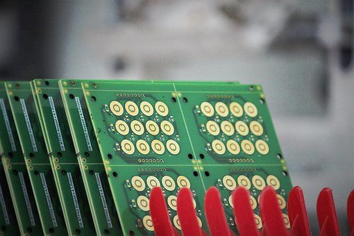
One sided, single layer MCPCBs are by far the most common configuration and are typically used for simple high-powered circuits such as an array of high power LEDS or power resistors.
For more complex circuits, PNC can add one or two additional laminate and copper layers, although the more layers that are added, the less effective the metal core is at removing heat, because there are more insulating layers of FR4 between the component and the core.
There are three methods to transfer the heat generated by a component like an UHB LED to the metal core in the PCB
1. Thermally conductive laminate
2. Milled openings in the laminate allowing direct component contact to the metal core
3. Plated heat transfer vias under the components
Typically, a MCPCB is fabricated using thin, thermally conductive laminates. These thermally conductive laminates are only 6-8 times more conductive than FR4 but they can transfer heat from a component if the laminate is thin and the heat transfer area is large enough. Typically, the heat from the components is conducted first to wide copper traces on the surface of the PC Board, which spreads the component’s heat over a wider area on the thermally conductive laminate. The heat is then transferred over this wide area down through the thermally conductive laminate and into the metal core.
For power components with larger footprints than an LED, such as DPAK and QFN packaged components, a more effective cooling technique is to mill a hole in the laminate underneath the component location. A thermal pad or thermally conductive epoxy can be used under the component to create a low resistance path to the core.
For multilayer boards, the best route is to use thermal vias to conduct the heat from the component thought the layers down to the copper layer closest to the metal core. The heat is then transferred from this copper layer down through the thermally conductive laminate to the metal core.
If you are designing a high-power circuit and want to increase component reliability or decrease the size of the product, talk to the experts at PNC. They can help you design a metal core Printed Circuit Board that will keep your circuit cool.